Home / Calculations / 01
Calculations · 01 · Member design
Floor system & member design
How the structural team picked a mass-timber floor and sized the steel under it: comparing three systems by demand/capacity ratio, checking the CLT panel for deflection and a two-hour fire, then measuring what the redesign saved in steel and carbon.
Three floor systems on the table
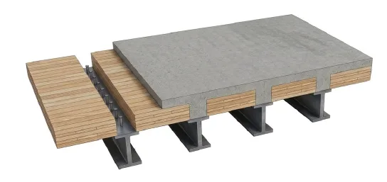
The owner required mass timber, but "use CLT" isn't a design. The team compared the existing concrete-on-steel-deck floor against two CLT options: one where the topping just sits on the panels, and one where shear studs pass through the CLT and make the topping act compositely with the steel beams.
| System | Topping | Deck / panel |
|---|---|---|
| Concrete–steel composite (base) | 3.5″ NWC, 145 pcf | 2″ Vulcraft 2.0D FL deck |
| CLT non-composite | 2″ NWC topping | Structurlam E4M3 139 ESP, 5-ply, t = 5.48″ |
| CLT composite (selected) | 3″ NWC topping | SmartLam E4M5.1, 5-ply, t = 5.875″ |
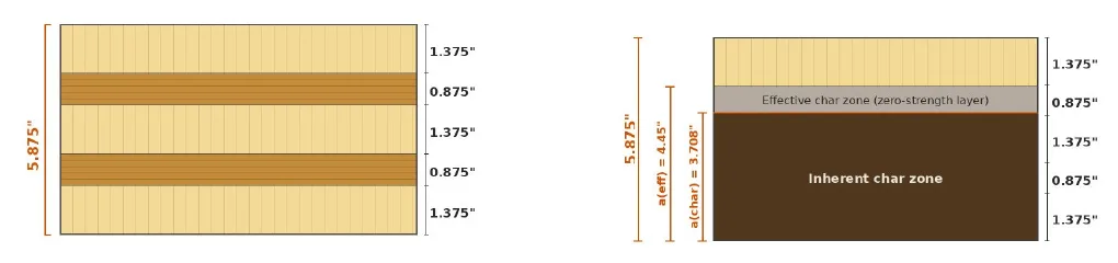
The selected panel is a 5-ply E4M5.1 layup of 1.375″ / 0.875″ / 1.375″ / 0.875″ / 1.375″ laminations (5.875″ total, 8.875″ with the topping, 17 psf). A single-span layout was used so bays with an odd number of infill members still work. The panel was selected for the worst-case bay, a 10′-9″ span, so one panel covers the whole building.
Concrete topping properties
The topping was increased from 2″ to 3″ of normal-weight concrete to add mass for vibration and stiffness for deflection. Its material properties come from standard relationships:
Values match Fig. S.1.6 on sheet S.1.
Demand / capacity ratios
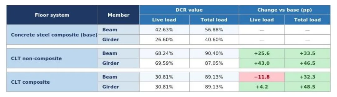
Each system's steel beams and girders were checked for strength and deflection. The demand/capacity ratio (DCR) says how much of a member's capacity is used. 100% is the limit, and a DCR well under 100% means steel is being wasted.
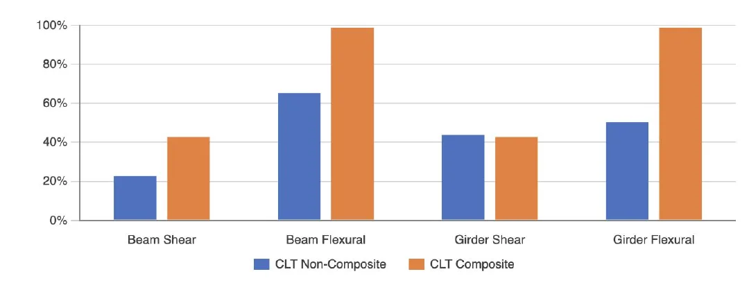
The base system's 41–57% deflection DCRs showed that the original structure was significantly over-designed. Both CLT systems came in around 90% on deflection. Strength decided between them: the composite system used its members to about 98% in flexure.
CLT panel deflection
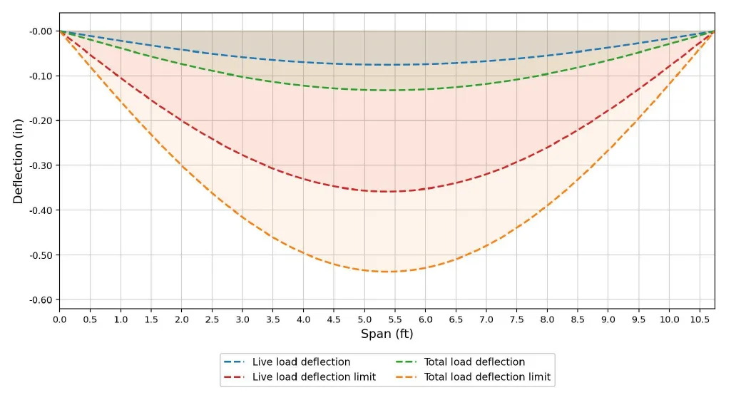
The steel checks don't cover the timber itself. CLT is orthotropic: its stiffness depends on the direction of each lamination. So the panel was checked separately over its 10.75 ft span, using the shear analogy method (U.S. CLT Handbook, Ch. 3) for effective bending and shear stiffness.
Two-hour fire: residual section
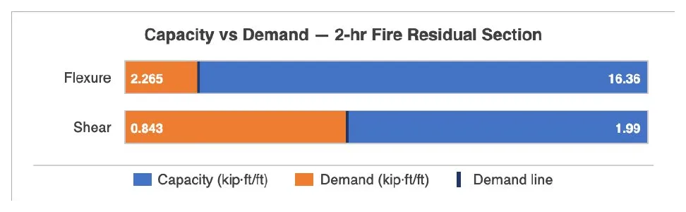
Instead of spray fireproofing, the team used the inherent charring method (NDS Ch. 16 with the manufacturer's guide). The panel is sized so that after two hours of burning, the wood that hasn't charred can still carry the load. It's predictable, needs no applied protection, and leaves the timber exposed.
Serviceability isn't checked after a fire because the panels would be replaced. Strength is, to make sure the floor holds up for safe egress and panel replacement.
Steel tonnage
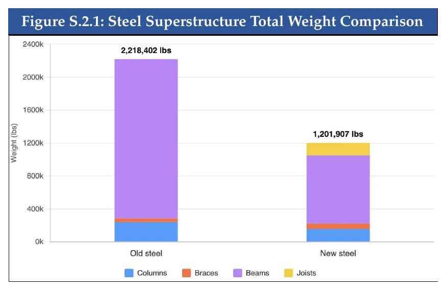
A lighter deck lowers gravity load all the way down the building, so beams, girders and columns could all be resized. In Zone 3, where loads were light, open-web steel joists replaced wide-flange beams. The average number of members per bay dropped from about 3 to 2.5.
| Columns (lb) | Joists (lb) | Braces (lb) | Beams (lb) | Total (lb) | |
|---|---|---|---|---|---|
| Original | 239,840 | — | 45,302 | 1,933,260 | 2,218,402 |
| Redesign | 156,897 | 152,230 | 64,045 | 828,735 | 1,201,907 |
Embodied carbon
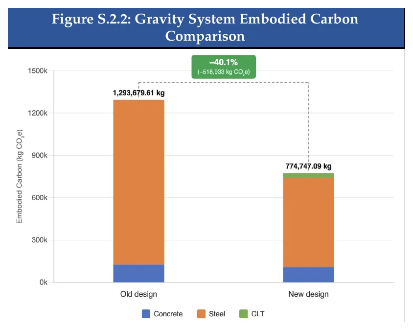
Each material's weight (converted to kg) is multiplied by its global warming potential (GWP) factor, in kg CO₂e per kg of material. CLT adds carbon back in, but much less than the steel it replaces.
| Material | GWP (kg CO₂e/kg) | Weight, old (lb) | Weight, new (lb) | CO₂e old (kg) | CO₂e new (kg) |
|---|---|---|---|---|---|
| Concrete | 0.30 | 930,417 | 930,417 | 126,591 | 126,591 |
| Steel | 1.16 | 2,218,402 | 1,201,907 | 1,167,088 | 632,316 |
| CLT | 0.20 | 0 | 374,000 | — | 33,924 |
| Total | 1,293,680 | 792,832 |
Foundations: the procedure
Three extra stories and a new coastal site meant the foundations had to be reconsidered. The foundation sheet sets out the design procedure the team followed:
- Determine soil parameters from the geotechnical report.
- Select the foundation systems to analyze.
- Identify loading from the structure: base axial and base shear (RAM reactions).
- Axial capacity design.
- Settlement analysis, evaluating the controlling settlement conditions.
- Lateral capacity design, spot-checking elements for gravity and lateral performance.
- Acoustics and vibration review of construction (OSHA limits on equipment use).
- Compare results to design goals and justify the best system.
Governing references: ASCE 7-22 Ch. 11, 12 and 20 (seismic parameters and site class), FBC 2023 Ch. 17–18 (testing, inspection and deep foundations), ACI 318-19, ASTM D1143 / D3966 (axial and lateral load tests) and ACI 336.1-24 (drilled shafts).