Home / Calculations / 02
Calculations · 02 · Analysis
Structural analysis & modeling
How load gets through the building and how it was modeled: the gravity load path, a RAM finite element model tuned for an orthotropic floor, the walking-vibration check, and torsion in the beams that carry the façade.
Loads into the model
Floor live loads come from ASCE 7-22 Ch. 4 by occupancy, reduced where the code allows. Mechanical and electrical rooms were set to a uniform 100 psf to allow for the extra equipment that three more stories bring. Façade weights from the enclosure design are applied as perimeter line loads.
| Program | Live load (psf) | Reduction |
|---|---|---|
| Corridor (1st floor / above) | 100 / 80 | Yes |
| Classrooms / lecture hall | 60 | Yes |
| Storage | 125 | Yes |
| Bathroom | 60 | No |
| Stairs | 100 | Yes |
| Open seating | 100 | No |
| Computer lab | 100 | Yes |
| Penthouse | 20 | No |
| Mechanical / electrical | 100 | No |
| Curtain wall line load | 0.295 klf | from AP.3 |
| Fiber cement wall line load | 0.231 klf | from AP.2 |
Live loads: Fig. S.1.7 on sheet S.1. The highlighted line loads are Tamara's assembly weights, rounded. See how they were calculated.
Gravity load path & takedown
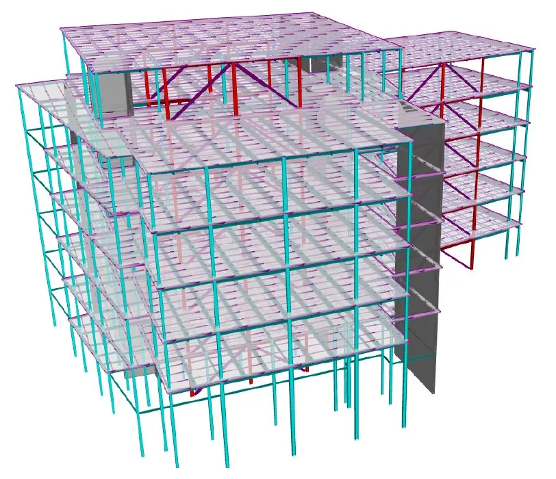
Load goes from the CLT deck to the secondary beams, then to the primary girders at each level, then down the columns to the foundation. The axial load in each column builds up story by story. Columns on the perimeter also pick up the façade line loads. RAM Structural System's Builder module did the member sizing and load takedown.
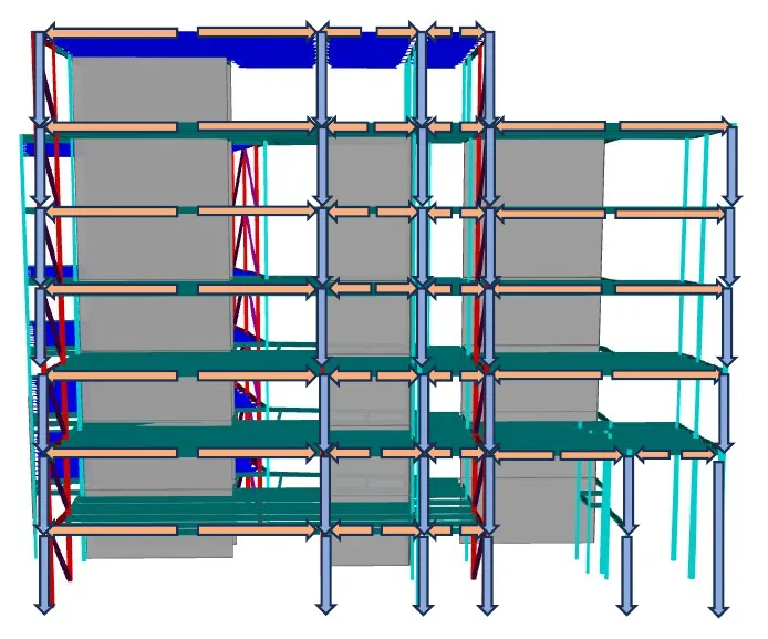
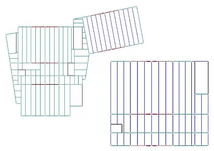
The framing layout also took constructability into account: repeating bay spacing for fabrication and erection, and as little angled framing as possible to avoid complicated connections and irregular load paths.
Modeling an orthotropic floor in RAM
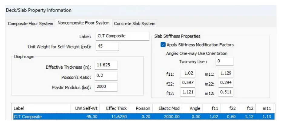
Modeled as a plain isotropic plate, a CLT–concrete floor is too stiff in one direction and too soft in the other. So the team derived orthotropic shell stiffness modifiers to scale the plate's bending (m), membrane (f), shear and torsion stiffness separately in each direction, using the Mass Timber Floor Vibration Design Guide (Ch. 9).
| Property | Value | Property | Value |
|---|---|---|---|
| Effective thickness | 11.625 in | Elastic modulus | 2,000 ksi |
| Poisson's ratio | 0.20 | Self-weight | 45 psf |
| f11 (membrane, strong) | 1.02 | m11 (bending, strong) | 1.129 |
| f22 (membrane, weak) | 0.597 | m22 (bending, weak) | 0.294 |
| f12 (in-plane shear) | 1.121 | m12 (torsion) | 0.511 |
Walking vibration
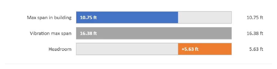
CLT has a high strength-to-weight ratio, low mass and little damping. A floor can pass every strength check and still feel bouncy. The FPInnovations method (U.S. CLT Handbook, Ch. 7) gives a maximum vibration-controlled span, and the 3″ topping was partly chosen to add mass.
Spandrel beam torsion
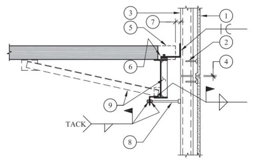
The heaviest façade (full-story GFRC framing, 230 plf) hangs off the slab edge, eccentric to the spandrel beam's shear center, so it twists the beam. Following AISC 360 and Design Guide 9, the team checked rotation of the controlling W18×40 spandrel and designed kickers back to the slab.
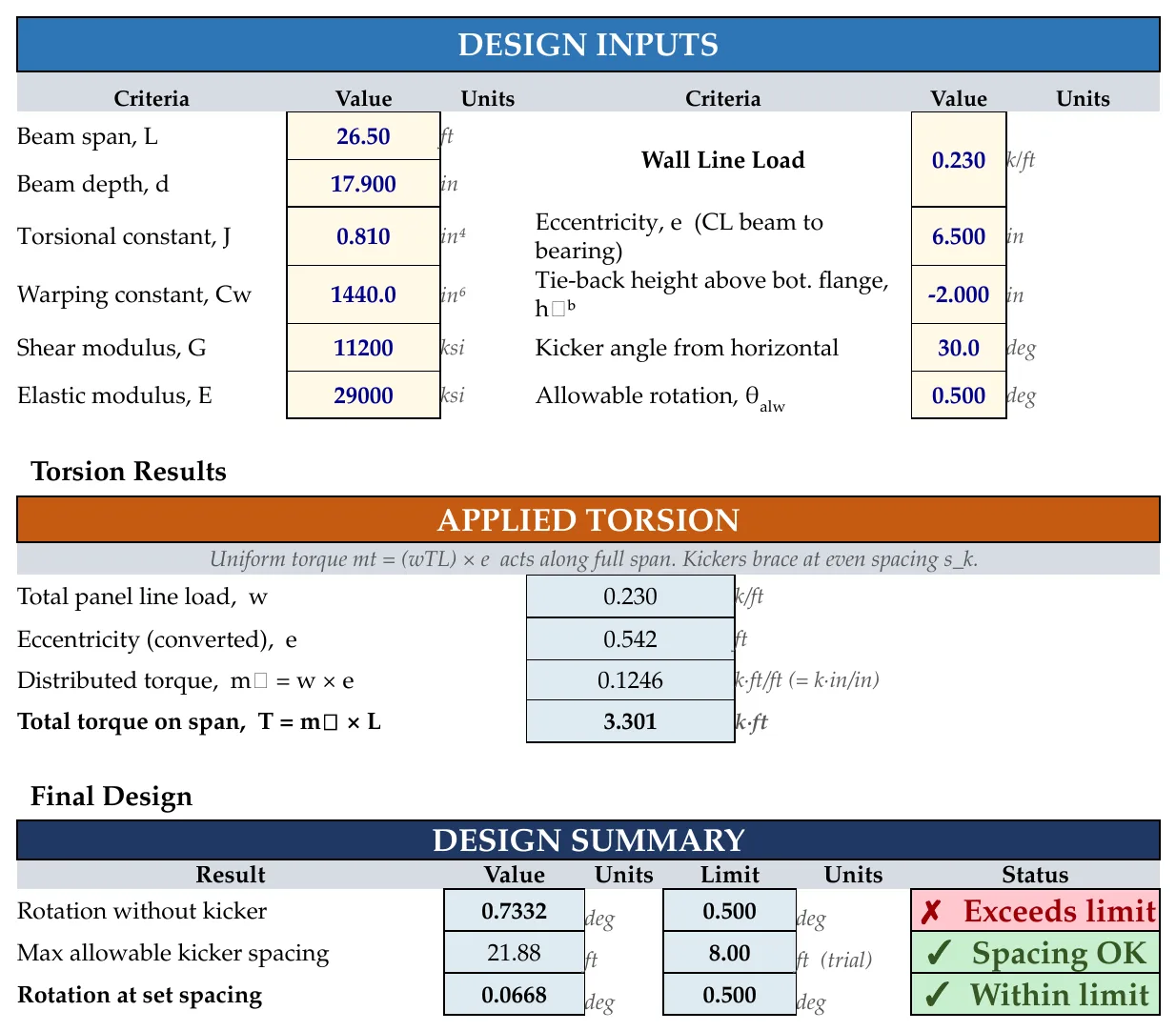
Torsion sheet authored by K. Regep.
Drift: analysis meets enclosure
Lateral analysis returns interstory drift, and the façade is what has to tolerate it. Tamara set the drift each enclosure system must accommodate under the 10-year service wind (D + 0.7W): h/600 at the ground floor and h/400 above. With h = 208 in, that's 0.35 in and 0.52 in.