Home / Calculations / 03
Calculations · 03 · Lateral loads
Wind: components & cladding
Tamara's hand calculations under ASCE 7-22 and the Florida Building Code, step by step: from a 180 mph basic wind speed to the force on every panel, window and bracket, and the drift each system has to absorb.
Why components & cladding
ASCE 7 handles wind in two ways. The main wind force resisting system (MWFRS) method finds the overall push on the building for the frame and bracing. The components & cladding (C&C) method finds the much higher local pressures that a single panel or window, and its fasteners, actually feel. These are highest at the building's edges and corners. Façade elements are designed with C&C, and in Boca Raton they're designed for hurricane wind.
Wind parameters
| Parameter | Value | Basis |
|---|---|---|
| Basic wind speed, V | 180 mph | Risk Category III, Boca Raton (ASCE Hazard Tool) |
| Exposure | C | Open coastal terrain |
| Velocity pressure coefficient, Kh | 1.27 | At mean roof height, Exposure C |
| Topographic factor, Kzt | 1.0 | No hill or escarpment |
| Directionality factor, Kd | 0.85 | Buildings, C&C |
| Ground elevation factor, Ke | 1.0 | Near sea level |
| Enclosure / GCpi | ±0.18 | Enclosed building |
| Floor-to-floor height | 17.33 ft | 17′-4″, six floors |
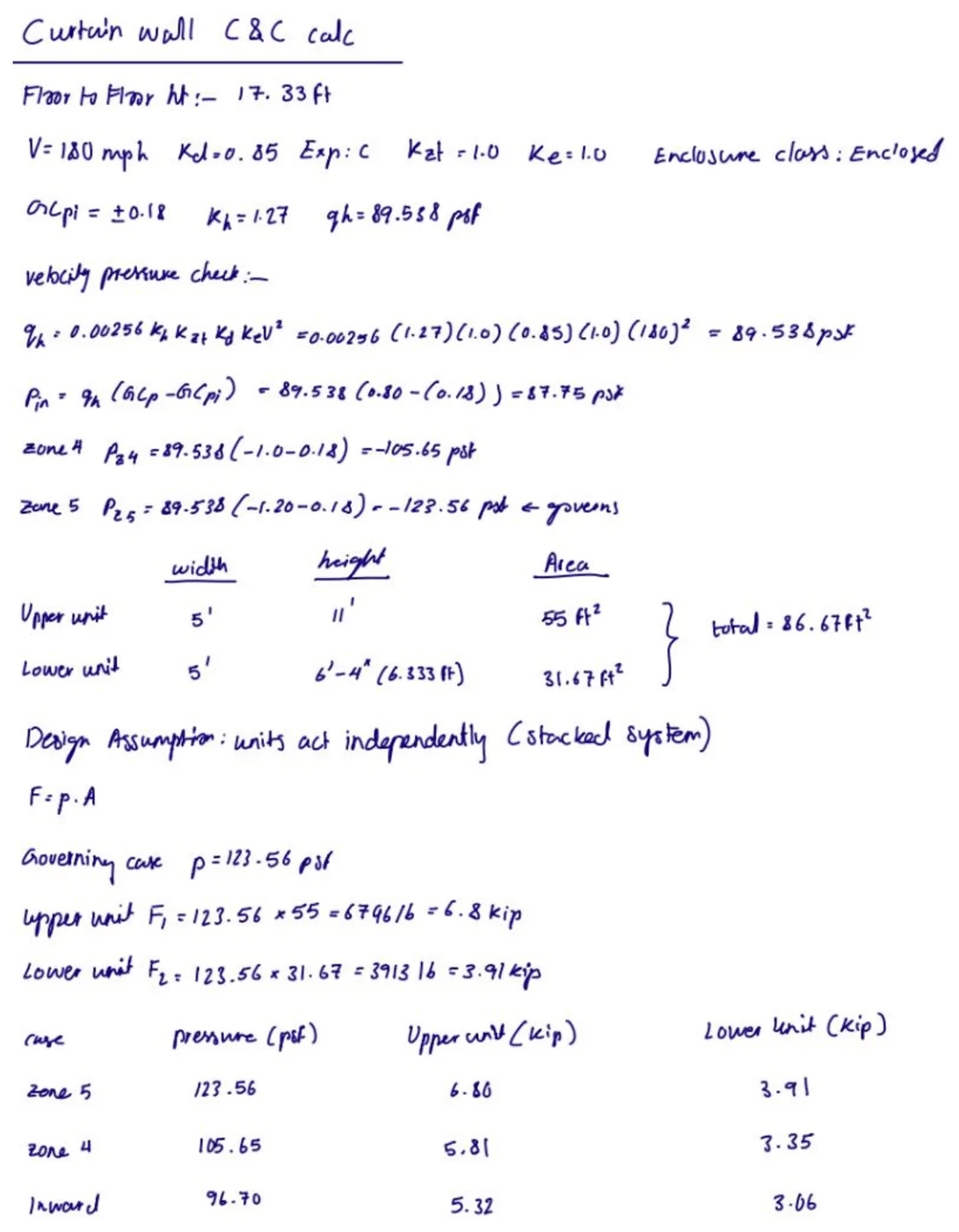
Velocity pressure
Design pressures by zone
Net pressure is external minus internal: p = qh[(GCp) − (GCpi)]. Internal pressure is taken with whichever sign makes it worse. Wall Zone 4 is the field of the wall. Zone 5 is the strip at each corner, where suction peaks.
Zone 5 suction was used as the design pressure for every enclosure system, which is conservative for panels in the field of the wall.
Panel forces: F = p · A
Each unit is checked on its own tributary area. The curtain wall's two stacked units are assumed to act independently, because they're separate modules.
| Element | Size | Area (ft²) | F, Zone 5 (kip) | F, Zone 4 (kip) |
|---|---|---|---|---|
| Curtain wall: upper unit | 5′ × 11′ | 55.00 | 123.56 × 55.00 = 6.80 | 5.81 |
| Curtain wall: lower unit | 5′ × 6′-4″ | 31.67 | 123.56 × 31.67 = 3.91 | 3.35 |
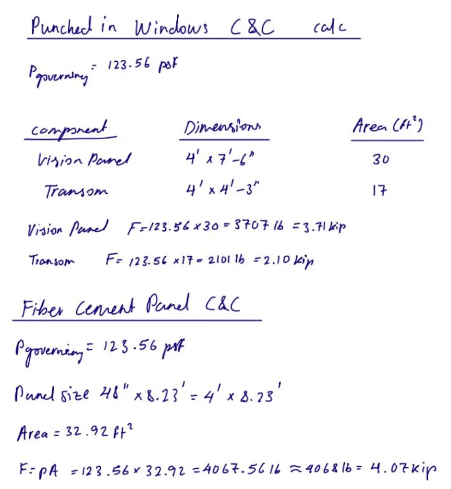
| Punched window: vision | 4′-0″ × 7′-6″ | 30.00 | 123.56 × 30.00 = 3.71 | — |
| Punched window: transom | 4′-0″ × 4′-3″ | 17.00 | 123.56 × 17.00 = 2.10 | — |
| Fiber cement panel | 4′ × 8.23′ | 32.92 | 123.56 × 32.92 = 4.07 | — |
Into the connections
A panel force means nothing until it reaches the structure. Each fiber cement panel hangs on 3 vertical rails with 3 brackets per rail (49″ o.c.). Every bracket stands 4″ off the stud wall, so it carries a moment as well as a reaction.
The curtain wall forces go to slab-edge anchors, and the window forces go to perimeter anchors in the stud wall. Connection details →
Effective wind area matters
A teammate's GFRC study ran the same C&C procedure in a spreadsheet for a façade module with a large effective wind area (1,400 ft²) and a mean roof height of 110 ft, on a 170 mph basis. GCp drops as effective area grows, because peak gusts don't load a large area all at once. So the governing pressures come out much lower:
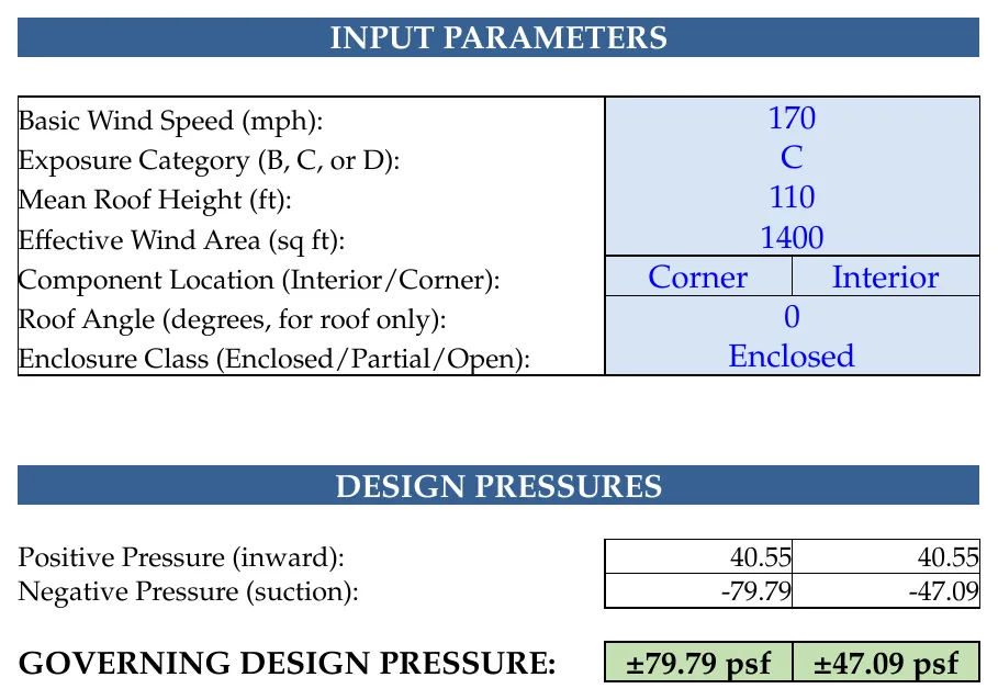
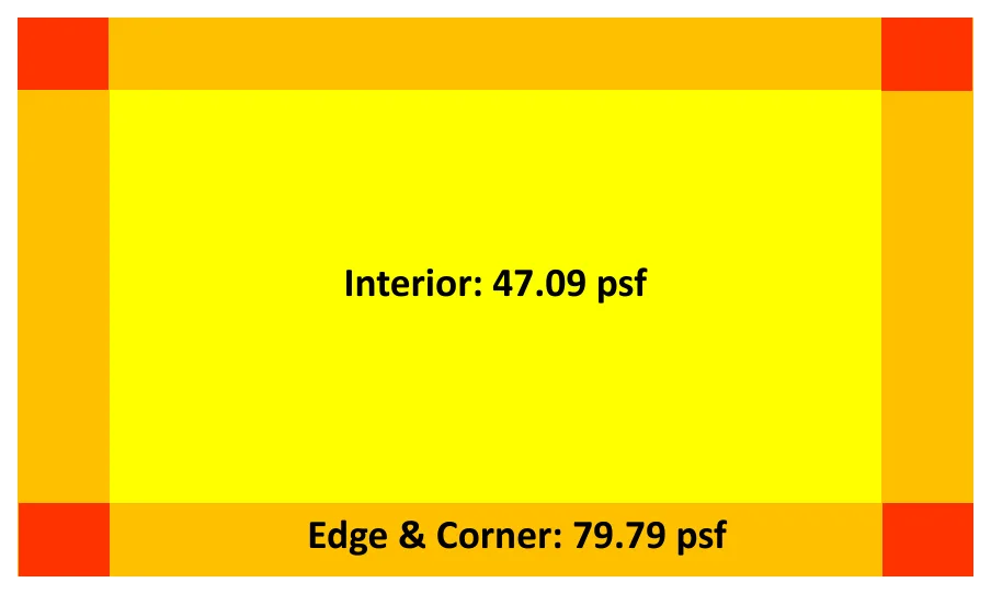
GFRC sheet authored by K. Regep.
Drift compatibility
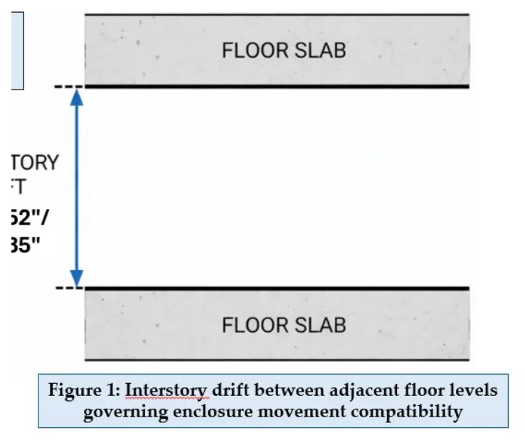
Strength is one check. Movement is the other. Enclosures span from slab to slab, so they have to absorb the building's interstory drift without cracking glass or tearing joints. Drift is checked at the service level using the 10-year MRI wind combination D + 0.7W.
| System | Required movement check | Preliminary status |
|---|---|---|
| Curtain wall | Stack joint / anchors ≥ 0.52 in | Feasible with movement joint |
| Punched window | Two side joints = 0.26 in each | Feasible with adequate perimeter joint |
| Fiber cement panels | Joint / rail tolerance ≥ 0.26 in each side | Feasible with flexible jointing |
The punched window splits the 0.52 in drift between its two side joints: 0.52 / 2 = 0.26 in each.